DNR-DIO-470 |
|||||||||||||||||||||||||||||||||||||||||||||||||||||||||||||||||||||||||||||||||||||||||||||||||||||||||||||||||||||||||||||||||||||||||||||||||||||||||||||||||||||||||||||||||||||
 |
|||||||||||||||||||||||||||||||||||||||||||||||||||||||||||||||||||||||||||||||||||||||||||||||||||||||||||||||||||||||||||||||||||||||||||||||||||||||||||||||||||||||||||||||||||||
| 10-Channel Electromechanical Relay Interface | |||||||||||||||||||||||||||||||||||||||||||||||||||||||||||||||||||||||||||||||||||||||||||||||||||||||||||||||||||||||||||||||||||||||||||||||||||||||||||||||||||||||||||||||||||||
 |
 |
||||||||||||||||||||||||||||||||||||||||||||||||||||||||||||||||||||||||||||||||||||||||||||||||||||||||||||||||||||||||||||||||||||||||||||||||||||||||||||||||||||||||||||||||||||
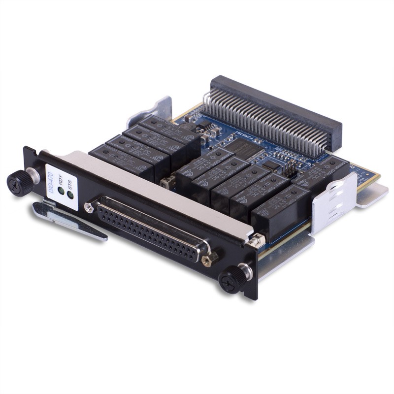
The DNR-DIO-470 is a 10-channel, high-current, electromechanical relay board for use with RACKtangle® chassis. The DIO-472 boards are designed for use in a wide variety of switching and digital control applications. Each channel is configured as a standard Form C (SPDT) relay and switches voltages up to 140 VDC or 150 VAC. Each channel is rated for continuous operation at 4 Amps @ 30 VDC and 5 Amps at 125 VAC. All relays default to “NC” on power up/reset. Switching rates up to 125 Hz are supported. Each relay is protected by an on-board 8 Amp fuse. All connections are made through a convenient 37-pin D connector ensuring no problems obtaining mating cables or connectors. To support the high current ratings, the DNx-DIO-470 board uses a special version of the 37-pin D connector. As UEI’s standard DNA-CBL-37 series cables and DNA-STP-37 should not be used with the DNx-DIO-470 unless the maximum current required will be less than 2 Amps. Please use the DNA-CBL-37HC and DNA-STP-37HC for applications switching 2 amps or more. The cables are available in 1, 3, 10 and 20 foot lengths. Each board provides 350 VDC isolation between channels, as well as between the board, cube and other installed I/O boards. The DNx-DIO-470 series includes software drivers supporting all popular operating systems including: Windows, Linux, QNX, VXWorks, RTX, and other popular Real-Time Operating Systems. Windows users may take advantage or the powerful UEIDAQ Framework which provides a simple and complete software interface to all popular Windows programming languages and data acquisition and control applications (e.g. LabVIEW, DASYLab, MATLAB). |
|||||||||||||||||||||||||||||||||||||||||||||||||||||||||||||||||||||||||||||||||||||||||||||||||||||||||||||||||||||||||||||||||||||||||||||||||||||||||||||||||||||||||||||||||||||
| Characteristics: | |||||||||||||||||||||||||||||||||||||||||||||||||||||||||||||||||||||||||||||||||||||||||||||||||||||||||||||||||||||||||||||||||||||||||||||||||||||||||||||||||||||||||||||||||||||
|
|||||||||||||||||||||||||||||||||||||||||||||||||||||||||||||||||||||||||||||||||||||||||||||||||||||||||||||||||||||||||||||||||||||||||||||||||||||||||||||||||||||||||||||||||||||
|
|||||||||||||||||||||||||||||||||||||||||||||||||||||||||||||||||||||||||||||||||||||||||||||||||||||||||||||||||||||||||||||||||||||||||||||||||||||||||||||||||||||||||||||||||||||


Comprar ahora

Buscar productos